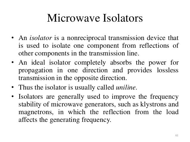
Working Principle Of Isolator In Microwave

Isolator Microwave Wikipedia

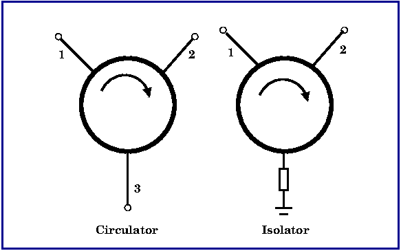
Isolator Circulator Basics

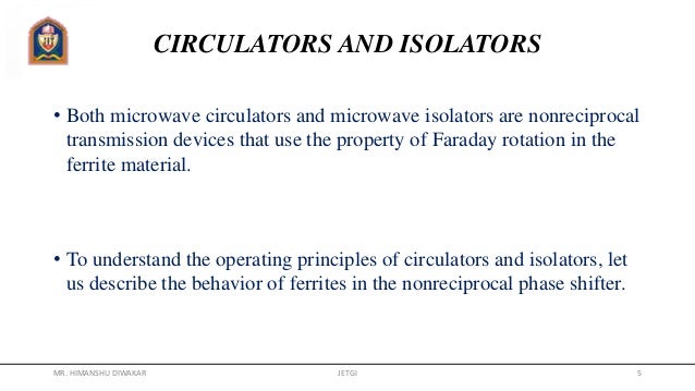
What Is Faraday Rotation In Ferrite Explain Working Of The Isolator Using Faraday Rotation
Microwave Engineering Basics
Https Valvo Com Wp Content Uploads 2017 12 Isolator Pdf
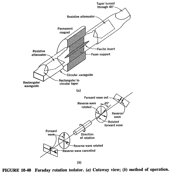
Waveguide Isolator And Circulators Faraday Rotation Isolator
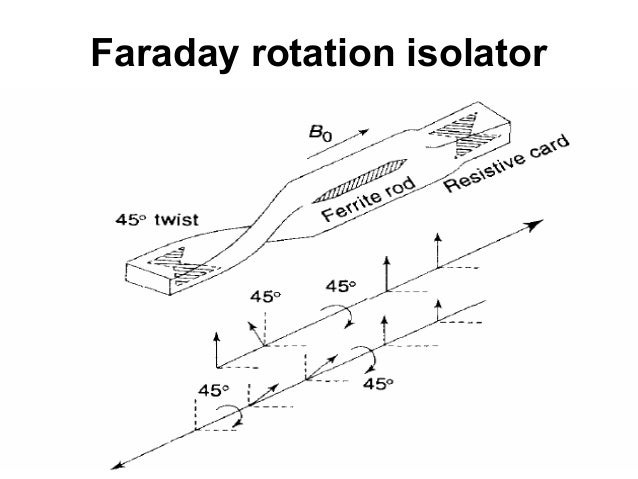
When the wave passes through mechanical twist bend the field polarization rotates by 450 in anticlockwise direction.
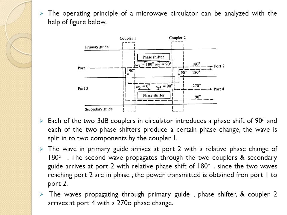
Working principle of isolator in microwave.

Explain Working Principle Of Isolator With Neat Sketch Also Compare Isolator And Circulator

Isolator In Microwave Youtube

Ferrite Isolators Or Circulators Characteristics And Uses Youtube
Rf And Microwave Components And Devices

Isolator In Microwave Working Internal Structure Applications Microwave Engineering Waveguide Youtube
A Primer On Circulators And Isolators Microwaves Rf
Chapter 2 Waveguide Components Applications Ppt Video Online Download

A Diagram Of Microwave Assembly 1 Isolator One Way Valve 2 Download Scientific Diagram
Https Valvo Com Wp Content Uploads 2017 12 Circulator Pdf
What Is An Electrical Isolator Types Of Isolators Working Applications
Microwave Propagation In Ferrites 23
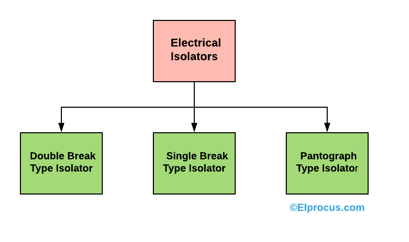
What Is An Electrical Isolator Types Operation And Its Applications

Schematics And Working Principle Of The Optical Isolator Circulator Download Scientific Diagram

What Is Optical Circulator Youtube

Optical Circulator An Overview Sciencedirect Topics
Short Tutorial Understanding Rf Isolator And Rf Circulators Electronics360

Fiber Optic Circulators Fosco Connect
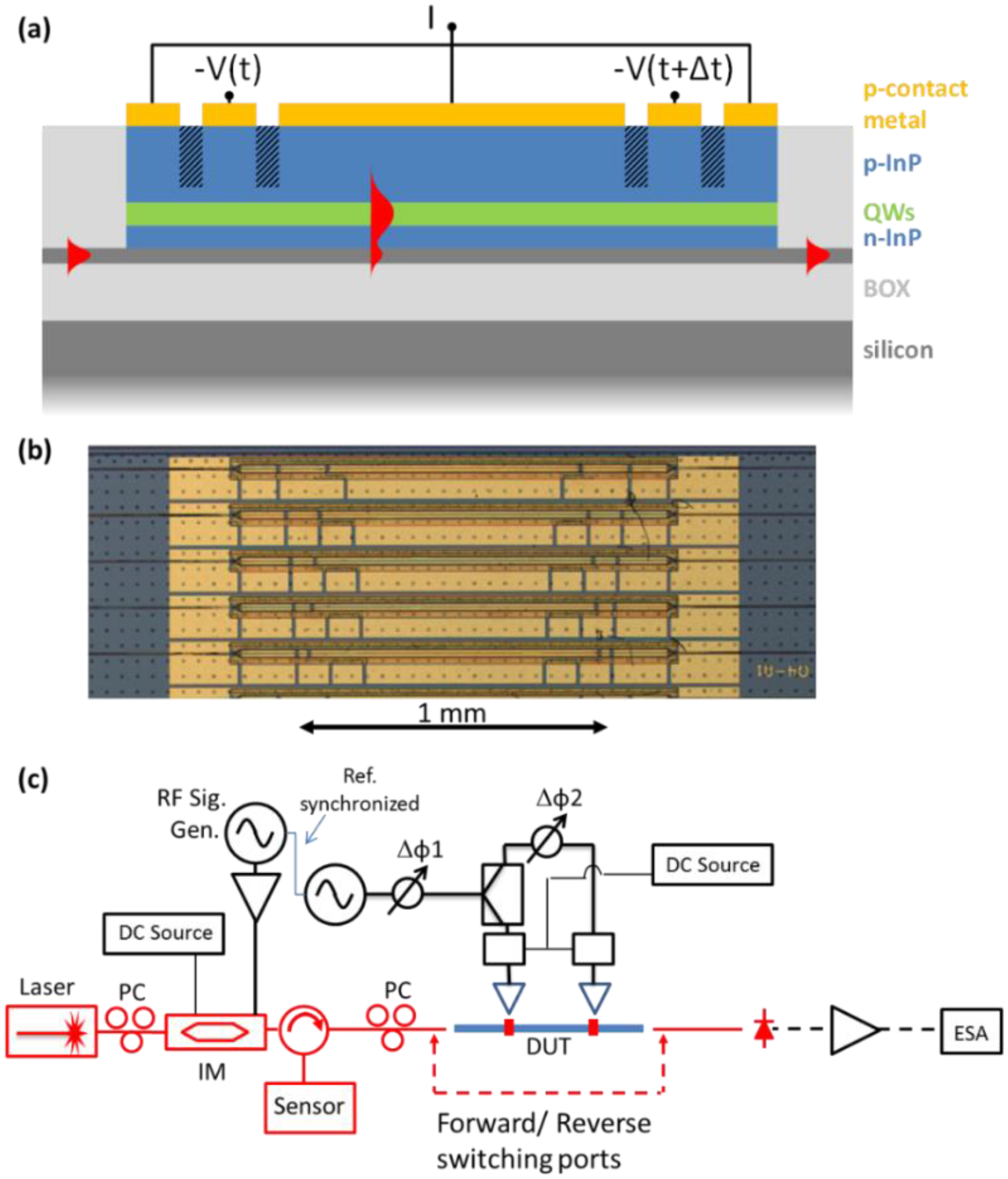
Photonics Free Full Text Integrated Microwave Photonic Isolators Theory Experimental Realization And Application In A Unidirectional Ring Mode Locked Laser Diode Html
Https Encrypted Tbn0 Gstatic Com Images Q Tbn 3aand9gcsylemo0c2fooft88l O09djaakigowdjkehkrjik0oz4xny P Usqp Cau

Circulators An Overview Sciencedirect Topics

Design Of Temperature Compensating Unit For The Circulator In 6 Mw 4 6 Ghz Lhcd System Sciencedirect

Structure And Principle Of Operation Of The Proposed Isolator A B Download Scientific Diagram

Optical Isolator Magnet Optical Isolator Working And Applications Magnets By Hsmag

Microwaves101 Phase Shifters
Source : pinterest.com
